🎧 Listen to the 60-Second Audio Recap:
This guide covers complete Mitsubishi AC Home Assistant ESPHome local control via ESP32-S3. The official Mitsubishi WF-RAC WiFi dongle works. It pairs quickly, the app is polished, and the integration is seamless. It also routes every power-on event, every temperature setpoint, and every schedule you create through Mitsubishi’s cloud servers in a foreign jurisdiction. A factory somewhere knows you turned on your AC at 11pm. It knows your sleep temperature. It knows when you left for work.
That is not a hypothetical privacy concern. That is the documented behavior of the product.
This guide eliminates it entirely. You will replace the cloud dependency with a local ESP32-S3 controller that communicates directly with your AC unit over its SPI bus. Control happens on your LAN, through Home Assistant, with zero manufacturer involvement. Sub-second response times. No subscription. No server outage risk.
We also address a specific gap that appears repeatedly in Reddit threads: most posts reference older ESPHome libraries for MHI units that target ESP8266 and the Arduino framework. On ESP32-S3 hardware, you need the Astute4185 fork, which is built specifically for the ESP-IDF framework and is significantly more stable on this architecture. This guide uses that fork exclusively.
Prerequisites & Hardware
Software Requirements
- Home Assistant (any recent version) running and accessible on your local network. If you need to set that up first, see our guide on installing Home Assistant OS on Proxmox.
- ESPHome Add-on installed via the Home Assistant Add-on Store.
- Chrome or Edge browser. These are required for the WebSerial API at
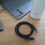
web.esphome.io. Firefox will not work. - A USB-C cable that carries data. Charge-only cables will not expose a COM port.
Hardware Comparison: Which Controller Do You Buy?
| Controller | Price | Chip | Notes |
|---|---|---|---|
| Nodo-shop ESPAC | ~€25 | ESP8266 | MHI-specific. Correct cable included. Easier setup. Limited stock. ESP8266 is a real constraint: less RAM, Arduino framework only, no ESP-IDF support. |
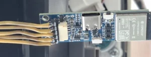
| Tinytronics Universal AC Controller | ~€15 | ESP32-S3 | The recommended path for this guide. Onboard bi-directional level-shifter (5V to 3.3V) and step-down converter (12V input). Requires manual pinout research and soldering. |
| Official WF-RAC Module | ~€90+ | Proprietary | Plug-and-play. Requires Smart M-Air app and a Mitsubishi cloud account. Zero local control. Covered in Method 1 below. |
This guide uses the Tinytronics Universal for the full local control path. It is the better hardware at a lower price. The trade-off is that it requires soldering skill and careful pinout work.
Additional Components Required (Tinytronics Route)
- JST-XH 5-pin (Female) to DuPont (Female) cable. Warning: standard cable wire colors do not match the MHI CNS pinout. You will remap them manually.
- 2.54mm pitch 90-degree male pin headers. These prevent you from soldering wires directly to the board pads, which makes future maintenance much easier.
- Soldering iron and solder.
- Multimeter with continuity or resistance mode. This is mandatory, not optional.
- Fine Stanley knife or scalpel for clearing solder bridges.
Method 1: The Quick Start (Beginner-Friendly, Cloud-Dependent)
Who This Is For
This method is for users who want plug-and-play without soldering. You accept the trade-offs: higher cost (~€60+), full cloud dependency, and no local control. If privacy is your primary concern, skip directly to Method 2.
Home Assistant integration is possible via the community-maintained mitsubishi_wf_rac HACS integration, but be clear on what that means: it is a cloud-polled integration. Your commands still travel to Mitsubishi’s servers and back. It is not local.
Step 1: Purchase and Install the WF-RAC Module
- Order the Mitsubishi WF-RAC module. Verify compatibility with your specific SRK-series unit before purchasing.
- Kill power to the indoor unit at the breaker panel. Wait 30 seconds.
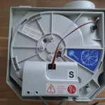
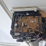
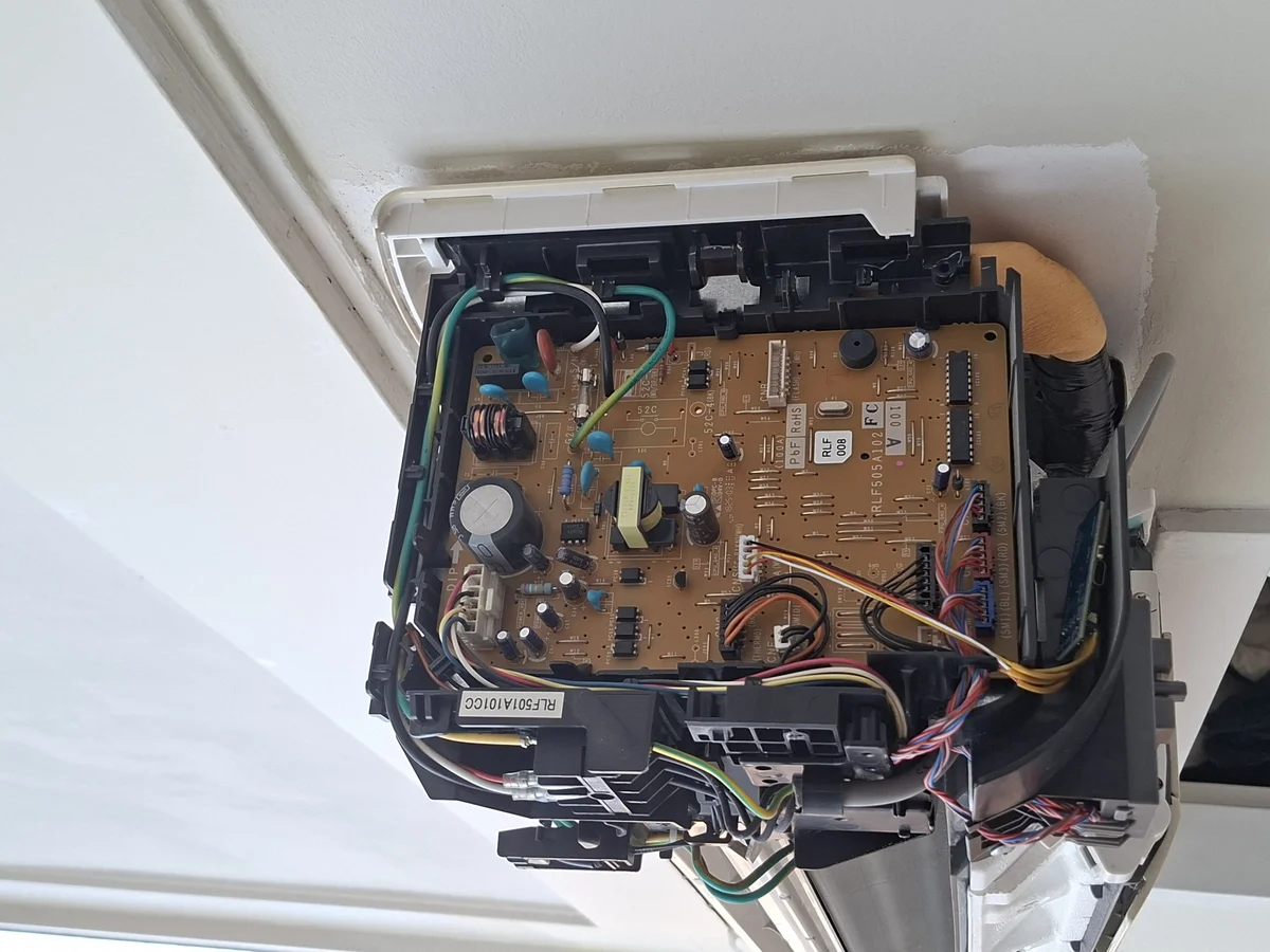
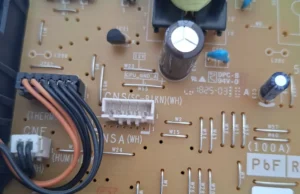
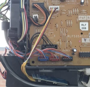
- Remove the indoor unit cover and locate the CNS port on the PCB. It is a small white connector, typically 5-pin.
- Insert the WF-RAC module. The connector is keyed and only fits one way.
- Restore power at the breaker.
Step 2: Configure via Smart M-Air App
- Download the Smart M-Air app on iOS or Android.
- Create a Mitsubishi cloud account.
- Follow the in-app pairing wizard to connect the module to your WiFi network.
All commands from this point forward route through Mitsubishi’s cloud infrastructure. Latency, privacy, and uptime are all outside your control.
Step 3: Optional Home Assistant Integration
- Install HACS in Home Assistant if it is not already present.
- Search for
mitsubishi_wf_racin the HACS integration store. - Add the integration via Settings > Devices & Services.
This gives you a Home Assistant climate entity, but the data path is still: Home Assistant > Mitsubishi cloud > your AC unit. You have not eliminated the cloud. You have added a nicer UI on top of it.
Method 2: Mitsubishi AC Home Assistant ESPHome — Full Local Control
This is the method that matters. Five steps from unboxed hardware to a fully local, sub-second-response climate entity in Home Assistant.
Step 1: Physical Preparation – Soldering and Measuring
The Tinytronics controller has five solder pads you need to work with: VIN, 21, 48, 34, and GND.
- Solder 90-degree male pin headers to all five pads. The 90-degree angle is important. It lets the connector sit flush against the board inside the AC unit without straining the joints.
- Critical check before proceeding: Set your multimeter to continuity or resistance mode. Test between pin
21and pin48. You must get zero continuity. These two pads sit very close together. An invisible solder bridge between them will cause persistent communication errors that look like a software problem but are entirely physical. If you get continuity, use your scalpel to clear the gap between the pads, then retest.
Now map your JST-XH to DuPont cable to the MHI CNS pinout. The MHI CNS port on SRK-series units (2018 and newer) is a 5-pin connector. The standard cable colors do not match, so follow this mapping explicitly:
| CNS Pin | Wire Color (Standard Cable) | ESP32 Pad | Function |
|---|---|---|---|
| Pin 1 | Black | GND |
Ground |
| Pin 2 | Red | 21 |
MISO |
| Pin 3 | White | 48 |
MOSI |
| Pin 4 | Yellow | 34 |
SCK / Clock |
| Pin 5 | Orange | VIN |
12V Power |
Verify that the black wire aligns with Pin 1 on the AC unit’s CNS connector. On most SRK-series units, Pin 1 is on the right side of the connector when viewed from the front. When in doubt, use your multimeter to confirm ground continuity before applying power.
Step 2: Create the ESPHome Device in Home Assistant
- Open Home Assistant and navigate to ESPHome in the sidebar.
- Click + NEW DEVICE in the bottom right corner.
- Click Continue and give your device a name. Something like
Airco Woonkamerworks well. Click Next. - Enter your WiFi SSID and password. Click Next. Note that the SSID is case-sensitive.
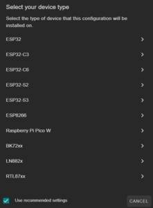
- Select the platform: choose ESP32-S3. This must match the chip on your Tinytronics controller.
- When you see the “Configuration created” screen, click Skip. You need to edit the YAML before flashing anything.
Step 3: Add the YAML Configuration
- Find your new device in the ESPHome dashboard and click EDIT.
- Locate the
esp32:block in the generated YAML. Verify that the framework is set toesp-idf. If it saysarduino, replace it. TheAstute4185library requires ESP-IDF and will not compile on the Arduino framework.
Your esp32: block should look exactly like this:
esp32:
  board: esp32-s3-devkitc-1
  framework:
    type: esp-idf
Now append the following to the bottom of your YAML file. Do not modify the indentation:
external_components:
  - source: github://Astute4185/MHI-AC-Ctrl-ESPHome_ESP-IDF@master
    components: [MhiAcCtrl]

MhiAcCtrl:
  frame_size: 20  # 20 = units circa 2018 | 33 = newer units
  sck_pin: 34
  miso_pin: 21
  mosi_pin: 48

climate:
  - platform: MhiAcCtrl
    name: "MHI Air Conditioner"
Click SAVE.
A note on the library choice: the Astute4185 fork was written specifically for the ESP-IDF framework on ESP32-S3 architecture. It runs significantly more stable than the original project on this hardware. This is the correct library for this hardware combination.
Step 4: First Flash via USB
The ESP32-S3 has no firmware yet, so the first flash must happen over a physical USB connection. After this, all future updates can be pushed wirelessly via OTA.
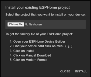
- In the ESPHome dashboard, click the three-dot menu (⋮) on your device and select Install.
- Choose Manual download, then Factory format.
- Wait for compilation to complete and the
.binfile to download. This typically takes 2 to 5 minutes on the first compile. - Connect the Tinytronics controller to your laptop via USB-C. Confirm the cable is data-capable.
- Open Chrome or Edge and navigate to
web.esphome.io. - Put the ESP32-S3 into bootloader mode using this exact sequence: hold the BOOT button, press and release the RESET button, then release BOOT.
- Click Connect in the browser, select the correct COM port from the list, click Install, and select the
.binfile you downloaded. - Wait for the flash completion confirmation before disconnecting.
Step 5: Physical Installation into the AC Unit
- Kill power at the breaker panel. Do not just use the remote or the wall switch. Cut mains power. Wait a minimum of 30 seconds.
- Remove the indoor unit cover. Locate the white CNS connector on the PCB. It is a small 5-pin JST-style connector.
- Insert your JST-XH cable into the CNS connector. Verify that the black wire (Pin 1) is on the correct side before applying any pressure.
- Route the cable and controller so neither is pinched by the cover.
- Restore power at the breaker.
- Wait approximately 60 seconds. Your device should appear as Online in the ESPHome dashboard.
- Navigate to Settings > Devices & Services in Home Assistant. The ESPHome device should appear for configuration. Add it to complete the integration.
Configuration and Validation
Reading the ESPHome Logs: What Good Looks Like
In the ESPHome dashboard, click LOGS on your device. A healthy connection produces output like this:
[I] ok20=1500 hdr6d=842 rx=0 tx=0Here is what each value tells you:
ok20incrementing: packets are being processed without errors. This is your primary health indicator.hdr6dorhdr6cincrementing: valid frame headers are being received from the AC unit.rx=0or very low: no receive errors on the SPI bus.
If ok20 is incrementing and rx is near zero, your hardware connection is solid.
Functional Validation Checklist
- 90-degree headers soldered. Continuity check between pins 21 and 48 passed (zero continuity).
- ESP32-S3 flashed via USB with factory format
.binfile. - Device appears Online in ESPHome within 60 seconds of AC power restore.
-
ok20counter incrementing in logs. - Temperature setpoint change in Home Assistant reflects in logs within 5 seconds.
-
Current Temperaturesensor populating in the Home Assistant climate entity.
The Honest Truth: Quirks and Real Limitations
This setup works well. It also has genuine quirks you should know about before you spend an evening debugging something that has a simple explanation.
SPI Bus Sensitivity on ESP32-S3
SPI communication on the ESP32-S3 is noise-sensitive. A solder joint that looks fine visually can produce intermittent errors under load. The symptom is a persistent rx=29 value in the logs. This is not a software problem. It is a marginal electrical connection. The fix is to reflow your solder joints and recheck continuity. Do not spend time adjusting YAML when the problem is physical.
The MHI Internal Bus Reset Requirement
After a failed connection attempt, the MHI internal communication bus can lock up in a state that prevents new connections. A software reboot of the ESP32 will not fix this. You must cut mains power at the breaker for at least 30 seconds. This is a hardware-level behavior of the Mitsubishi SRK-series PCB. It is not an ESPHome bug and it is not something you can work around in software.
Frame Size Ambiguity
The frame_size parameter accepts either 20 or 33. There is no definitive public list mapping specific unit model numbers to the correct value. The wrong value causes erratic behavior: the AC may turn on when commanded off, or ignore mode changes entirely. Start with frame_size: 20 for units from around 2018. If behavior is erratic, switch to 33 and do a full power cycle. Trial and error is currently the only reliable method.
Tinytronics vs. ESPAC: The Real Trade-off
The ESPAC from Nodo-shop is genuinely easier for MHI specifically. The correct cable is included, the pinout is documented for MHI, and there is no soldering required beyond basic assembly. The limitation is real though: the ESP8266 chip has less RAM, runs only the Arduino framework, and does not support ESP-IDF. For long-term stability and future ESPHome feature support, the ESP32-S3 on the Tinytronics is the better foundation. The cost of that is soldering skill. A cold joint on this board costs hours of debugging.
Troubleshooting Common Errors
Error: t_low or t_high Incrementing, ok Stays at 0
Cause: The ESP32 is not receiving the SCK clock signal from the AC unit. Without the clock, no SPI communication is possible.
Fix: Check the DuPont connector on pin 34. Verify it is making solid contact with CNS Pin 4 (the yellow wire). Remove and reseat the connector. Check for a bent pin on the header.
Log pattern that indicates this problem:
[I] t_low=847 t_high=0 ok=0 rx=0Error: AC Behaves Erratically – Turns On When Commanded Off
Cause: The frame_size value in your YAML does not match the communication protocol used by your specific AC unit generation.
Fix: Edit your YAML and change the frame size:
# Change this:
frame_size: 20
# To this:
frame_size: 33
Save the file, trigger an OTA update from the ESPHome dashboard, and then perform a full mains power cycle on the AC unit. Both steps are required.
Error: Solder Bridge Between Pins 21 and 48
Cause: A short circuit between the MISO line (pin 21) and the MOSI line (pin 48) on the ESP32 board. The two pads are adjacent and a hair of solder between them is enough to cause this.
Fix: Disconnect power from both the ESP32 and the AC unit immediately. Inspect the solder pads between pins 21 and 48 under magnification or a bright light. Use your scalpel to clear any material bridging the gap. Retest with your multimeter in continuity mode. Do not reconnect to AC power until the continuity test confirms zero connection between those two pins.
Error: Device Flashes Successfully but Never Appears Online in ESPHome
- Verify your WiFi credentials in the YAML. The SSID is case-sensitive. A capital letter difference will prevent connection silently.
- Confirm the ESP32-S3 and your Home Assistant instance are on the same network subnet. A guest network or VLAN separation will block mDNS discovery.
- Check the ESPHome Add-on logs in Home Assistant for mDNS discovery errors.
- Try triggering an OTA update from the ESPHome dashboard. If the device is reachable on the network, this will confirm connectivity even if mDNS is not resolving correctly.
Automation Ideas to Build Next
Your AC unit is now a fully local Home Assistant climate entity. Here is where it gets useful.
Solar Overproduction Cooling
Trigger cooling mode automatically when your solar inverter reports excess generation above a threshold. This uses energy that would otherwise be exported at a low feed-in tariff to pre-cool your home.
automation:
  - alias: "Solar Overproduction - Start AC Cooling"
    trigger:
      - platform: numeric_state
        entity_id: sensor.solar_inverter_excess_power
        above: 1500
        for:
          minutes: 5
    action:
      - service: climate.set_hvac_mode
        target:
          entity_id: climate.mhi_air_conditioner
        data:
          hvac_mode: cool
      - service: climate.set_temperature
        target:
          entity_id: climate.mhi_air_conditioner
        data:
          temperature: 22
Window Sensor Interlock
Link a Zigbee window or door sensor to the AC. When the window opens, the AC turns off. When it closes, it resumes. This prevents cooling an open room. If you have not yet set up Zigbee sensors in Home Assistant, our guide on pairing your first Zigbee sensor with Home Assistant ZHA covers the full process.
automation:
  - alias: "Window Open - Turn Off AC"
    trigger:
      - platform: state
        entity_id: binary_sensor.living_room_window
        to: "on"
    action:
      - service: climate.turn_off
        target:
          entity_id: climate.mhi_air_conditioner

  - alias: "Window Closed - Resume AC"
    trigger:
      - platform: state
        entity_id: binary_sensor.living_room_window
        to: "off"
    action:
      - service: climate.turn_on
        target:
          entity_id: climate.mhi_air_conditioner
Presence-Based Pre-Cooling
Combine the climate entity with a person entity and GPS zone tracking. Trigger pre-cooling 20 minutes before estimated arrival based on your phone’s location leaving a defined zone. Your home is at the right temperature when you walk in, without running the AC all day.
What You Have Achieved
The Mitsubishi WF-RAC cloud dependency is gone. Your AC unit responds to Home Assistant commands in under a second, entirely on your local network. No manufacturer server sits between your automation and your hardware. No subscription. No outage risk from a server you do not control.
The specific problems this guide solved that Reddit threads consistently leave open:
- Which controller to buy for MHI: the Tinytronics Universal with ESP32-S3 is the correct answer for the pro path.
- Which ESPHome library to use on ESP32-S3: the
Astute4185fork with ESP-IDF framework, built specifically for ESP32-S3 architecture and significantly more stable than the original project on this hardware. - Why communication errors appear: solder bridge between pins 21 and 48, not a software issue.
- Why the AC locks up after a failed attempt: the MHI internal bus requires a mains power cycle, not just an ESP32 reboot.
Your AC is now a proper local smart home device. Build on it.